<data:blog.pageTitle/> | electronic | computer | elektro | komputer |komputer murah| jual komputer murah| microcontroller| diskon <data:blog.pageName/> |<data:blog.title/> Internet Marketing Web Directories

Wednesday, May 30, 2007

POWER SUPPLY ATX PC 200W

Source :: http://www.pavouk.org/hw/en_atxps.html


This power supply circuit uses chip TL494. Similar circuit is used in the most power supplies with output power about 200W.Device use push-pull transistor circuit with regulation of output voltage.

Line voltage goes through input filter circuit (C1, R1, T1, C4, T5) to the bridge rectifier. When voltage is switched from 230V to 115V, then rectifier works like a doubler. Varistors Z1 and Z2 have overvoltage protect function on the line input.
Thermistor NTCR1 limits input current until capacitors C5 and C6 are charged. R2 and R3 are only for discharge capacitors after disconnecting power supply. When power supply is connected to the line voltage, then at first are charged capacitors C5 and C6 together for about 300V.
Then take a run secondary power supply controlled by transistor Q12 and on his output will be voltage. Behind the voltage regulator IC3 will be voltage 5V, which goes in to the motherboard and it is necessary for turn-on logic and for "Wake on something" functions.
Next unstabilized voltage goes through diode D30 to the main control chip IC1 and control transistors Q3 and Q4. When main power supply is running, then this voltage goes from +12V output through diode D.

Stand-By mode

In stand-by mode is main power supply blocked by positive voltage on the PS-ON pin through resistor R23 from secondary power supply. Because of this voltage is opened transistor Q10, which opens Q1, which applies reference voltage +5V from pin 14 IO1 to pin 4 IO1. Switched circuit is totally blocked. Tranzistors Q3 and Q4 are both opened and short-circuit winding of auxiliary transformer T2.Due to short-circuit is no voltage on the power circuit. By voltage on pin 4 we can drive maximum pulse-width on the IO1 output. Zero voltage means the highest pulse-width. +5V means that pulse disappear.

Now we can explain function of running power supply.

Somebody pushes the power button on computer. Motheboard logic put to ground input pin PS-ON. Transistor Q10 closes and next Q1 closes. Capacitor C15 begins his charging through R15 and on the pin 4 IC1 begins decrease voltage to zero thanks to R17. Due to this voltage is maximum pulse-width continuosly increased and main power supply smoothly goes run.

In a normal operation is power supply controlled by IC1. When transistors Q1 and Q2 are closed, then Q3 and Q4 are opened. When we want to open one from power transistors (Q1, Q2), then we have to close his exciting transistor (Q3, Q4). Current goes via R46 and D14 and one winding T2. This current excite voltage on base of power transistor and due to positive feedback transistor goes quickly to saturation. When the impulse is finished, then both exciting transistors goes to open. Positive feedback dissapears and overshoot on the exciting winding quickly closes power transistor. After it is process repetead with second transistor. Transistors Q1 and Q2 alternately connects one end of primary winding to positive or negative voltage. Power branch goes from emitor of Q1 (collector Q2) through the third winding of exciting transformer T2. Next throug primary winding of main transformer T3 and capacitor C7 to the virtual center of supply voltage.

Output voltage stabilisation

Output voltages +5V and +12V are measured by R25 and R26 and their output goes to the IC1. Other voltages are not stabilised and they are justified by winding number and diode polarity. On the output is necessary reactance coil due to high frequency interference.
This voltage is rated from voltage before coil, pulse-width and duration cycle. On the output behind the rectifier diodes is a common coil for all voltages. When we keep direction of windings and winding number corresponding to output voltages, then coil works like a transformer and we have compensation for irregular load of individual voltages.
In a common practise are voltage deviations to 10% from rated value. From the internal 5-V reference regulator (pin 14 IC1) goes reference voltage through the voltage divider R24/R19 to inverting input(pin 2) of error amplifier. From the output of power supply comes voltage through divider R25,R26/R20,R21 to the non inverting input (pin 1). Feedback C1, R18 provides stability of regulator. Voltage from error amplifier is compared to the ramp voltage across capacitor C11.
When the output voltage is decreased, then voltage on the error amplifier is toodecreased. Exciting pulse is longer, power transistors Q1 and Q2 are longer opened, width of pulse before output coil is grater and output power is increased. The second error amplifier is blocked by voltage on the pin 15 IC1.

PowerGood

Mainboard needs "PowerGood" signal. When all output voltages goes to stable, then PowerGood signal goes to +5V (logical one). PowerGood signal is usually connected to the RESET signal.

+3.3V Voltage stabilisation

Look at circuit connected to output voltage +3.3V. This circuit makes additional voltage stabilisation due to loss of voltage on cables. There are one auxiliary wire from connector for measure 3.3V voltage on motherboard.

Overvoltage circuit

This circuit is composed from Q5, Q6 and many discrete components. Circuit guards all of output voltages and when the some limit is exceeded, power supply is stopped.
For example when I by mistake short-circuit -5V with +5V, then positive voltage goes across D10, R28, D9 to the base Q6. This transistor is now opened and opens Q5. +5V from pin 14 IC1 comes across diode D11 to the pin 4 IC1 and power supply is blocked. Beyond that goes voltage again to base Q6. Power supply is still blocked, until he is disconnected from power line input.


ATX Power Connector

Pin Signal Color 1 Color 2 Pin Signal Color 1 Color 2
1 3.3V orange violet 11 3.3V orange violet
2 3.3V orange violet 12 -12V blue blue
3 GND black black 13 GND black black
4 5V red red 14 PS_ON green grey
5 GND black black 15 GND black black
6 5V red red 16 GND black black
7 GND black black 17 GND black black
8 PW_OK grey orange 18 -5V white white
9 5V_SB violet brown 19 5V red red
10 12V yellow yellow 20 5V red red

Labels:

Voltage Controlled Switch using 555 Timer

Source :: http://www.zen22142.zen.co.uk/Circuits/Switching/vcs555.htm

Circuit :
Miroslav Adzic - Serbia & Montenegro

Description:
In this circuit the 555 timer is used in a novel way, as a voltage controlled switch.

Notes:
The old and omnipresent NE555 can be very good at something it was not meant for: driving relays or other loads up to 200 mA. The picture shows an example circuit: if the input level rises over 2/3 of the supply voltage - it will turn on the relay, and the relay will stay on until the level at the input drops below one third of the supply voltage.

If the relay and D1 were connected between pin 3 and ground, the relay would be activated when the input voltage drops below one third, and deactivated when the input voltage goes over two thirds of the supply voltage.

It is also a nice advantage that the input requires only about 1 uA, which is something bipolar transistors can't compete with. (This high impedance input must not be left open.) A large hysteresis makes the circuit immune to noise. The output (pin 3) can only be either high or low (voltage-wise), and it changes its state almost instantenously, regardless of the input signal shape.

The voltage drop across the NE555's output stage (at 35-100 mA) is 0.3-2.0 V, depending on the way the relay is connected and the exact current it draws. D1 is absolutely vital to the safety of the integrated circuit.

Labels:

24 Hour Timer by IC 4060

Source :: http://www.zen22142.zen.co.uk/Circuits/Timing/24hour.htm

Circuit : Ron J
Email Ron

Description:
These two circuits are multi-range timers offering periods of up to 24 hours and beyond. Both are essentially the same. The main difference is that when the time runs out, Version 1 energizes the relay and Version 2 de-energizes it. The first uses less power while the timer is running; and the second uses less power after the timer stops. Pick the one that best suits your application.

Notes:
The Cmos 4060 is a 14 bit binary counter with a built in oscillator. The oscillator consists of the two inverters connected to Pins 9, 10 & 11; and its frequency is set by R3, R4 & C3.The green Led flashes while the oscillator is running: and the IC counts the number of oscillations. Although it's a 14 bit counter, not all of the bits are accessible. Those that can be reached are shown on the drawing.

By adjusting the frequency of the oscillator you can set the length of time it takes for any given output to go high. This output then switches the transistor; which in turn operates the relay. At the same time, D1 stops the count by disabling the oscillator. Ideally C3 should be non-polarized; but a regular electrolytic will work, provided it doesn't leak too badly in the reverse direction. Alternatively, you can simulate a non-polarized 10uF capacitor by connecting two 22uF capacitors back to back (as shown).

Using "Trial and Error" to set a long time period would be very tedious. A better solution is to use the Setup tables provided; and calculate the time required for Pin 7 to go high. The Setup tables on both schematics are interchangeable. They're just two different ways of expressing the same equation.

For example, if you want a period of 9 Hours, the Range table shows that you can use the output at Pin 2. You need Pin 2 to go high after 9 x 60 x 60 = 32 400 seconds. The Setup table tells you to divide this by 512; giving about 63 seconds. Adjust R4 so that the Yellow LED lights 63 seconds after power is applied. This will give an output at Pin 2 after about 9 Hours.

The Support Material for the timers includes a detailed circuit description - parts lists - a step-by-step guide to construction - and more. A suitable Veroboard layout for each version is shown below:

The timer was designed for a 12-volt supply. However, provided a suitable relay is used, the circuit will work at anything from 5 to 15-volts. Applying power starts the timer. It can be reset at any time by a brief interruption of the power supply. The reset button is optional; but it should NOT be used during setup. The time it takes for the Yellow LED to light MUST be measured from the moment power is applied. Although R1, R2 and the two LEDs help with the setup, they are not necessary to the operation of the timer. If you want to reduce the power consumption, disconnect them once you've completed the setup. If you need a longer period than 24-hours, increase the value of C3.


Labels:

555 Asymmetric Timer

Source :: http://www.zen22142.zen.co.uk/Circuits/Timing/asym.htm

Circuit : Andy Collinson
Email: anc@mitedu.freeserve.co.uk

Description:
A timer circuit with independent mark and space periods.

Notes:
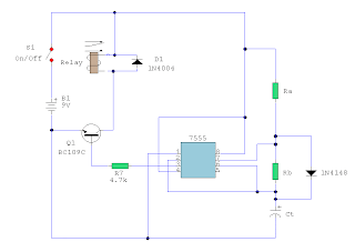
A simple astable timer made with the 555, the mark (on) and space (off) values may be set independently. The timing chain consists of resistors Ra, Rb and capacitor Ct. The capacitor, Ct charges via Ra which is in series with the 1N4148 diode. The discharge path is via Rb into into pin 7 of the IC. Both halves of the timing period can now be set independently.

The charge time (output high) is calculated by:

T(on) = 0.7 Ra Ct

The discharge time (output low) is calculated by:

T(off) = 0.7 Rb Ct

Please note that the formula for T(on) ignores the series resistance and forward voltage of the 1N4148 and is therefore approximate, but T(off) is not affected by D1 and is therefore precise.

Labels:

Tuesday, May 29, 2007

Other gates made with NAND

Source :: http://www.doctronics.co.uk/4011.htm

An important property of NAND gates is that they can be linked to perform the functions of other logic gates. In fact, any logic function can be implemented using only NAND gates:
If you have designed a system which needs a NAND gate, a NOT gate and an AND gate, you might think of using a separate integrated circuit for each logic function. This would leave you with a circuit in which there were three unused NAND gates, five unused NOT gates and three unused AND gates. It is a lot more efficient (and cheaper) to use NAND gates to implement the other functions. All three gates can be made with just one 4011 integrated circuit.

Labels:

4011 : 2-input NAND gates (easy IC )

Source :: http://www.doctronics.co.uk/4011.htm


Pin connections

The 4011 has four separate 2-input NAND
gates which you can use independently.

Truth table

The truth table of each individual gate is:

input B input A output
0 0 1
0 1 1
1 0 1
1 1 0

where '0' represents a LOW voltage, and '1' represents a HIGH voltage.

Labels:

Dark Activated Switch by IC 741

Source :: http://www.zen22142.zen.co.uk/Circuits/Switching/darksw.htm

Circuit :
Andy Collinson
Email: anc@mitedu.freeserve.co.uk

Description:
This circuit will activate a relay when light falls to a preset level. Light level can be adjusted with VR1 and the relay contacts may be used to operate an external light or buzzer.
Notes:
The light sensor used is the ORP12 photocell. In bright light the resistance of the ORP12 can be as low as 80 ohm and at 50lux (darkness) the resistance increases to over 1 Mohm. The 1M control should provide a wide range for light intensities, if not its value may be increased. The op-amp senses the voltage difference between pins 2 and 3. The control VR1 is adjusted so that the relay is off, the output of the op-amp will be around 2 Volts. When light falls, the resistance of the photocell increases and the difference in input voltage is amplified by the op-amp, the output will swing towards full supply and drive the transistor and relay. The 270k resistor provides a small amount of hysteresis, so that the circuit switches on and off with slightly different light levels. This eliminates relay chatter. Take great care if you decide to wire the relay to activate a mains lamp. Make sure the relay contacts provide adequate isolation and have ample rating for the load.

Parts List:
ORP12 Photocell (1)
RLY1: 12VSPDT (1)
U1: UA741 (1)
Q1: BC109 NPN (1)
D1: 1N4002 DIODE (1)
F1: 1A (1)
VR1: 1M RESISTOR (1)
ORP12: 500K RESISTOR (1)
R1,R3,R2: 10k RESISTOR (3)
R5: 4.7k RESISTOR (1)
R6: 1k RESISTOR (1)
R4: 270k RESISTOR (1)

Labels:

CD4001 Light Detector Circuit

Source :: http://www.zen22142.zen.co.uk/Circuits/Switching/ldet.htm
Kindly submitted by Mick Devine from the UK

Notes:
Variable resistor R1 adjusts the light threshold at which the circuit triggers. R1's value is chosen to match the photocells resistance at darkness. The circuit uses a CMOS 4001 IC. Gate U1a acts as the trigger, U1b and c form a latch. S1 resets the circuit. The output device may be a low power piezo buzzer.

Labels:

555 Timer 5 to 30 Minute

Source :: http://www.zen22142.zen.co.uk/Circuits/Timing/5_30timer.htm


Circuit : Andy Collinson
Email: anc@mitedu.freeserve.co.uk

Descriptipn:
A switched timer for intervals of 5 to 30 minutes incremented in 5 minute steps.

Notes:
Simple to build, simple to make, nothing too complicated here. However you must use the CMOS type 555 timer designated the 7555, a normal 555 timer will not work here due to the resistor values. Also a low leakage type capacitor must be used for C1, and I would strongly suggest a Tantalum Bead type. Switch 3 adds an extra resistor in series to the timing chain with each rotation, the timing period us defined as :-

Timing = 1.1 C1 x R1


Note that R1 has a value of 8.2M with S3 at position "a" and 49.2M at position "f". This equates to just short of 300 seconds for each position of S3. C1 and R1 through R6 may be changed for different timing periods. The output current from Pin 3 of the timer, is amplified by Q1 and used to drive a relay.

Parts List:
Relay 9 volt coil with c/o contact (1)
S1: On/Off (1)
S2: Start (1)
S3: Range (1)
IC1: 7555 (1)
B1: 9V (1)
C1: 33uF CAP (1)
Q1: BC109C NPN (1)
D1: 1N4004 DIODE (1)
C2: 100n CAP (1)
R6,R5,R4,R3,R2,R1: 8.2M RESISTOR (6)
R8: 100k RESISTOR (1)
R7: 4.7k RESISTOR (1)

Labels:

Monday, May 28, 2007

1MHZ Digital Frequency Meter

Source :: http://users.otenet.gr/~athsam/frequency_meter.htm


This circuit is a frequency meter, low cost. It covers region 1HZ until 1MHZ. The IC1 schmitt trigger that it regulates the signal of entry and him changes in reasonable level suitable for the IC2-3-4. With the tenth pulse in the entry of IC2/1, is produced a pulse '' carry '' in the IC3/5. The same moment the IC2 causes the depiction in the DIS1, show [0], the IC3 causes the DIS2, to show [ 1 ]. When in the entry of IC3 it reaches and the tenth pulse, the DIS2 show [ 0 ] and the DIS3 show [ 1 ], (with total depiction 100, having the display in right order). The exit '' carry'' off IC4/5, can be used in order to it turns on the decimal point (comma) the DIS1, in order to it shows a situation over the limits of measurement. The timed begins with the one of half double timer (IC5A). Switch S1 select the interruption the time in 1sec or in 1ms. At the duration of this interruption, second half the (IC5B), it produces a interruption of depiction 2 or 3sec., at the duration which counter cut off by the entry and the displays remain OFF. In the end of depiction, a pulse RESET, begins the interruption of time/depiction. The critical point is round the Q1-IC1, which should be placed as long as it becomes more near in the jack of entry, to reject of parasitic signals of high frequency. For the regulation, we can use a frequency meter good precision (if you do not have you are lented) and a generator of signal. We put switch S1, in place [HZ], we apply in the entry a low frequency and we regulate the trimmer TR2, so that we take the right clue, which should suit with source frequency meter. We repeat also the regulation for the department of KHZ, with a higher frequency. The supply of circuit becomes with a battery +9V, if it is used as portable or from suitable power supply if it is incorporated in some unit that exists already.


Part List

R1= 8.2Mohm C5= 2.2uF 16V IC2-3-4= 4026
R2-9= 100Kohm C6= 10uF 16V IC5= 556
R3= 470Kohm C7= 10nF 63V Mylar IC6= 4007
R4= 470 ohm C8-10= 1nF 63V Mylar IC7= 7805
R5-6-7= 10Kohm C9= 1uF 16V DS1-3=Display 7segment Comm. Cath.
R8= 3.3Mohm TR1= 1M ohm trimmer S1= ON-OFF mini switch
C1-2= 1uF 63V Mylar TR2= 1Kohm trimmer S2= 1X2 mini switch
C3= 47uF 16V Q1= 2N930
C4= 100nF 63V IC1= 4583 [Dual Schmitt Trigger]

Labels: ,

12V Car Battery Charger

Source : http://users.otenet.gr/~athsam/car_12v_battery_charger.htm


The usual chargers of battery automotive, are simple and cheap appliances that charge continuously the battery, with a rythm of few amperes, for the time where the appliance is ON. If the holder do not close in time the charger, the battery will overcharge and her electrolytic faculty are lost with evaporation or likely exists destruction of her elements. The charger of circuit exceeds these faults. It checks electronic the situation of charge of battery and it has circuit of control with retroaction, that forces the battery charge with biggest rythm until charge completely. When charge completely, it turns on one RED led (LD2). The charger has been drawn in order to charge batteries of 12V, ONLY. What should watch it from what it manufactures the circuit, they are the cables that connect the transformer with the circuit and in the continuity the battery, should they are big cross-section, so that heat when it passes from in them the current of charge and also they do not cause fall of voltage at the way of current through them.

  • Adjustment

After assembling of the circuit, adjust TR1 to null value, power-up and make the following adjustments :-

[1] Without connecting the battery check that the 2 LED�s are turned on.

[2] Connect a car battery to the circuit and check that LD2 is OFF and a current (normally 2A to 4A) is flowing to the battery.

[3] Adjust TR1 until LD2 turns ON and the charge current is cut.

[4] Adjust TR1 to null value and charge the battery using the hydrometer technique (if you do not have or do not know how to use a hydrometer, then use a good condition battery and charge).

Carefully adjust TR1 so that LD2 begins to turn ON and the charge current falls to a few hundred milliamps (mA). If TR1 is set correctly then in the next round of charging you will noticed LD2 begin to flicker as the battery is being charged. When battery is completely charged, LD2 turns ON completely.TR1 does not need further adjustment anymore. Q1 is connected in line with the battery and is fired by R3, R4 and LD2. The R2, C1, TR1 and D2 sense the voltage of the battery terminal and activate Q2 when the voltage of the battery terminal exceeds the value predetermined by TR1. When an uncharged battery is connected, the terminal voltage is low. Under this circumstance, Q2 is turned OFF and Q1 is fired in each half cycle by R3, R4 and LD2. The Q1 functions as a simple rectifier and charges the battery. If the battery terminal voltage is increased above the level that had been fixed by TR1, then Q2 shifts the control of Q1 gate. This deactivates Q1 and cuts off the current supply to the battery and turns LD2 ON indicating that the charge has been completed. Q1 and bridge rectifier GR1 should be mounted on heatsinks to prevent overheating. M1 is a 5A DC ammeter to measure the charge current.

Mini Stereo MIXER MIC-LINE for PC Audio Card

Source : http://users.otenet.gr/~athsam/audio_mixer_pc.htm

Most cards of sound in computer, are deprived stereo input for microphone, on the contrary have stereo input for high level [ Line ]. The circuit uses the input Line of card of sound, in order to we place a two mono stereo microphone, in the input of card of sound. Simultaneously he is more functionnal, after we have the possibility of regulating the gain of stage of microphone and regulating the final level of sound externally and independent for each channel of microphone. This solution was selected in order to we can if we want mixing two mono microphones. Also exist the classic supply for Electret microphones. Simultaneously exist stereo input Line, with two choices plugs of input and regulation level of input with the RV4, making him mix of sounds from the microphones and the input Line, easy affair. The input A, use two plugs RCA [ JF3-4 ] and input B, use a classic stereo plug jack 3.5 mm of nail. The IC2A-B, make the addition of signals and they drive the stereo output, that becomes from the JF6 jack. In JF7, we can give the supply, bigger than + 9Vdc, from a simple external power pack. This voltage is stabilised in + 5V, from the IC3. This low voltage was selected in order, to does not exist danger overdrive of card of sound. If the level, is not in the level that we want, we can change the prices of resistors R14-19 and R21 until R24, with other smaller or bigger, so that we change also the percentage of gain of proportional stage.


Part List

R1-8-31-32=3.3Kohms C1-4-7-9-12-17=10uF 16V IC1=TLC274
R2-7-27-30=100ohms C2-8=470nF 63V MKT IC2=TLC272
R3-4-9-10=1Mohms C3-24-27-28=100nF 63V MKT IC3=7805
R5-11-21-22-23-24=10Kohms C5-10=10pF ceramic D1=1N4007
R6-12-15-17=1Kohms C6-11=1uF 16V D2=LED 3mm
R13-14-19-20-28-29=47Kohms C13-16-20-21=47pF JF1-2-5-6=female jack 3.5mm stereo
R18-16-25-26=22Kohms C14-15-18-19=1uF 63V MKT JF3-4=RCA female plug
RV1=2X100Kohms Lin. C22-23-25=100uF 16V JF7=female jack 3.5mm mono
RV2-3=47Kohms log. C26=4.7uF 16V
RV4=2X47Kohms log. C29=470uF 25V All the Resistors is 1/4W 1% metal film

Labels:

LM317 - Adjustable Regulator 1.5V

Sorce : http://www.national.com/pf/LM/LM317.html

Features


Guaranteed 1% output voltage tolerance (LM317A)
Guaranteed max. 0.01%/V line regulation (LM317A)
Guaranteed max. 0.3% load regulation (LM117)
Guaranteed 1.5A output current
Adjustable output down to 1.2V
Current limit constant with temperature
P + Product Enhancement tested
80 dB ripple rejection
Output is short-circuit protected


General Description


The LM117 series of adjustable 3-terminal positive voltage regulators is capable of supplying in excess of 1.5A over a 1.2V to 37V output range.

Labels:

LM741 - Op-AMP (Operational Amplifier)

General Description
The LM741 series are general purpose operational amplifiers which feature improved performance over industry standards like the LM709


Source : http://www.national.com/pf/LM/LM741.html

Labels:

Sunday, May 27, 2007

LM8560 Digital Clock 24 Hr with alarm

Circuit LM8560 Digital Clock 24 Hr with alarm
PCB LM8560 Digital Clock 24 Hr with alarm

Labels:

Super Flashing Light by C1061

Circuit Super Flashing Light by C1061

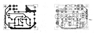
PCB Super Flashing Light by C1061

Labels:

Saturday, May 26, 2007

2 BC548 Transistor FM Voice Transmitter

Source :: http://www.zen22142.zen.co.uk/Circuits/rf/2bjttx.htm

Take care with transmitter circuits. It is illegal in most countries to operate radio transmitters without a license. Although only low power this circuit may be tuned to operate over the range 87-108MHz with a range of 20 or 30 metres.

Notes:
I have used a pair of BC548 transistors in this circuit. Although not strictly RF transistors, they still give good results. I have used an ECM Mic insert from Maplin Electronics, order code FS43W. It is a two terminal ECM, but ordinary dynamic mic inserts can also be used, simply omit the front 10k resistor. The coil L1 was again from Maplin, part no. UF68Y and consists of 7 turns on a quarter inch plastic former with a tuning slug. The tuning slug is adjusted to tune the transmitter. Actual range on my prototype tuned from 70MHz to around 120MHz. The aerial is a few inches of wire. Lengths of wire greater than 2 feet may damp oscillations and not allow the circuit to work. Although RF circuits are best constructed on a PCB, you can get away with veroboard, keep all leads short, and break tracks at appropriate points.

One final point, don't hold the circuit in your hand and try to speak. Body capacitance is equivalent to a 200pF capacitor shunted to earth, damping all oscillations. I have had some first hand experience of this problem. The frequency of oscillation can be found from the theory section,and an example now appears in the Circuit Analysis section.

Labels:

Tuesday, May 22, 2007

Circuit Video Amplifier by transistor BC547 & BC557

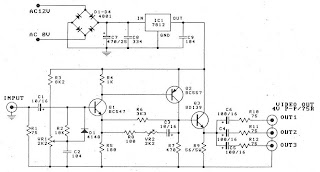
Circuit Video Amplifier by transistor BC547 & BC557

PCB Video Amplifier by transistor BC547 & BC557

Labels:

Circuit Sound SCR Swith by IC 1458 & SCR C106D

Circuit Sound SCR Swith by IC 1458 & SCR C106D


PCB Sound SCR Swith by IC 1458 & SCR C106D

Labels:

Circuit Light Relay Switch By BC547 & BC337


Circuit Light Relay Switch By BC547 & BC337

PCB Light Relay Switch By BC547 & BC337

Labels:

Egg Timer By 555


Circuit Egg Timer By 555

Labels: ,

555 Table Lamp Circuit

Circuit 555 Table Lamp Circuit

Labels:

Door Buzzer by NE555 + LM386


Circuit Door Buzzer by NE555 + LM386

Labels: ,

Sunday, May 20, 2007

LED Chaser by IC 4017 + IC 555


Circuit LED Chaser by IC 4017 + IC 555

Labels:

Timer Circuit by FET + Transister


Circuit Timer Circuit by FET + Transister

Labels:

ZN1034E Timer circuit


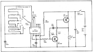
Circuit ZN1034E Timer circuit

Labels:

Simple Timer by CA3140 + NE555

Circuit Simple Timer by CA3140 + NE555

Labels:

CMOS Monostable by 4011


Circuit CMOS Monostable by 4011

Labels:

Dooebuzzer with 555

Circuit Dooebuzzer with 555

Labels:

Christmas Tree Lights Flasher with 7812+LM380

Circuit Christmas Tree Lights Flasher with 7812+LM380

Labels:

Friday, May 18, 2007

Water Alarm with LM350


Circuit Water Alarm with LM350

Labels:

Touch Switch By IC 4001 & 4020

Circuit Touch Switch By IC 4001 & 4020

Labels:

Supply Splitter with IC 741& TIP41,TIP42

Circuit Supply Splitter with IC 741& TIP41,TIP42

Labels:

Light Sensitive Switch with LDR + 2N2926


Circuit Light Sensitive Switch with LDR + 2N2926

Labels:

FET Overload Current Trip

Circuit FET Overload Current Trip

Labels:

Dfferential Temperature Relay Switch by IC 741

Circuit Dfferential Temperature Relay Switch by IC 741

Labels:

D.M.M. To Stopclock Converter with CA3140


Circuit D.M.M. To Stopclock Converter with CA3140

Labels:

555 IC Timer control relay Switch


Circuit 555 IC Timer control relay Switch

Labels:

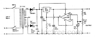
5-13V Power Supply with IC 7805 & CA3140


Circuit 5-13V Power Supply with IC 7805 & CA3140

Labels:

Thursday, May 17, 2007

Opto-Thermo Control Relay Switch with IC 741


Circuit Opto-Thermo Control Relay Switch with IC 741

Labels: ,

Two Tone Alarm with IC LM3900


Circuit Two Tone Alarm with IC LM3900

Labels: